
This is a cross post from my blog at makeawesomesh.it.  It is a little late but I hope it is still useful. All of the code used can be pulled from this github repo.
The Idea:
This project came out of the Hackathon LVL1 had in June 2012. The rules were minimal but had a big impact on the end product. The competition ran from noon Saturday till noon Sunday, so 24 hours. We had access to all of the tools at LVL1 plus we could bring our own tools, but we could not have any of the tools integrated as part of the final project. Each team was given an Arduino and a bread board. All other material has to come out of the LVL1 boneyard (this is the collection of stuff that has been donated for the purpose of hacking in any way we wish.) The goal was to make anything you want.
We had the weeks leading up to the event to look around the boneyard and think about what we thought we could make. We started with a list of things we wanted to make then limited that down to things we thought we had the parts to make. We tentatively settled on a 3D scanner. We knew we had all of the parts to make it but there was no guarantee that they would still be there the day of the hackathon as the boneyard was still being used normally by the hackerspace.
The Bones:
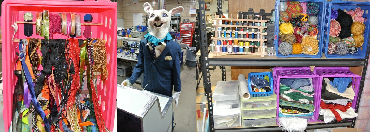
This is what all went into the scanner. Most of them are common around any house, others are not as common but could easily be replaced with parts or built from other things you would have around the house.
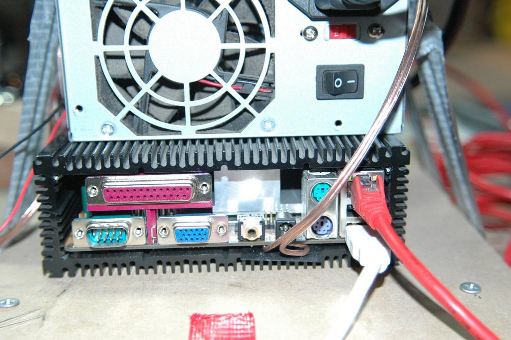
- Car computer (It is a low powered computer that runs a VIA x86 processor and runs off of 12VDC. Any computer will do)
- ATX power supply (This was a bad power supply that no longer worked to power a computer but the 5V and 12V rails still worked so we could use it to power everything we had)
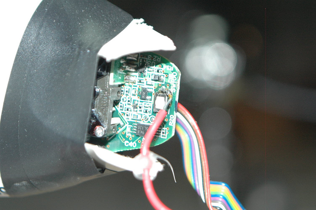
- Webcam (This was a really bad webcam and one of the limiting factors to the output file)
- Barcode scanner (This one is not so common but you can use a laser level from the hardware store or a laser pointer with a line lens on it)
- Arduino
- Ethernet cable
- Turntable (This was an automated turntable that was used to turn a 52inch TV before the motor went bad in it. We pulled the bad one out of it and put in a new one scavenged from an old printer)
- A few discrete components (the MOSFET was hard to find, but I found one inside of a portable battery pack along with a diode so we could switch the power to the turntable motor)
- Scrap lumber, Paint, hotglue, wire, pizza boxes to keep everything in place.
That is all that is needed to build the scanner. You may have noticed a few things missing from the list such a monitor, mouse, keyboard. LCDs typically get snatched up fast to run the various computer controlled tools around the space, so we did not have any in the boneyard. We were able to use monitors from other non hackable computers in the space to get it up and running but per the rules, could not have them as a requirement to use the final project. It was decided that the interface would be a web interface so that any devices on the network could be used to start a scan.
-
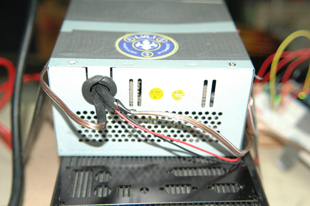
Old ATX power supply no longer worked for powering a full computer but was still able to power the low power computer and the turntable.
-
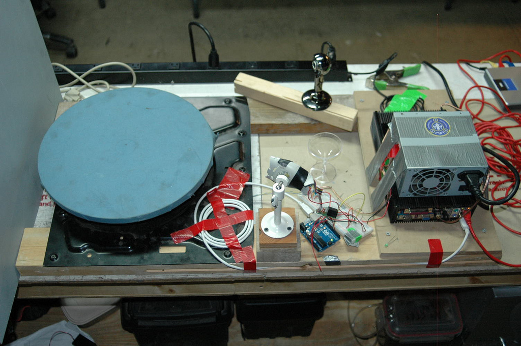
Sure looks like it was made out of a pile of junk.
The Brains:
So before we get into the code I want to remind everyone that not only was this a project built in 24 hours, but most of the coding had to be at the end of that time frame as we to have the hardware set up before we had anything to work with. We were sleep deprived and running on caffeine and nerd bliss by the time we dove into coding. What this lead to is code that follows no coding standards, very inefficient, and may possibly run in illogical circles chasing it's own tail. Keep this in mind when you look at it and try to restrain yourself from yelling, crying, or losing faith in humanity before taking it out on the Internet.
The computer itself is running Debian Linux with Apache, PHP, and Python installed on it. Linux because it is easier that way, and we did not have a copy of windows even if we wanted to use it. Apache and PHP are used because it was what the person doing that part felt most comfortable with and what they thought they could get running the quickest. PHP is used to generate a webpage that dynamically displays previously scanned items based on what images are available. It also calls bash scripts that are used to run the scan process by calling the camera to take images, send serial data to the arduino to fire the laser, and pulse the DC motor in the turn table. When all of this has to be done repetitively (full scans not just individual calls) a daemon is triggered that handles it.
Python did the image processing. The script is very short and operates by calling with and passing it arguments for the directory that holds the images, along with the name you want the output file to be. The script will then get a list of files from the directory, filter out any unrelated files, and sort them. This leaves it with a list of images in the order they are taken as the platform rotates. The heavy lifting in the script is handled by PIL. The script has it open each image and return an array with only the red values in the image. It then looks at each line and locates the pixel with the highest red value. After each one is found in an image, the array off pixel offsets and image rotation is passed to a function that calculates the XYZ location of each pixel. Finally it writes this data out to a very minimal wavefront object file (.obj).
Calculating the XYZ locations
All of the calculations are in this small code block
def calxyz(this, Px, sliceangle, h):
   mx = ((((Pw-Px)/math.sin(theta))*ctw)/((Pw-Pc)/math.sin(theta)))-ctw
   if mx > 0:
      return [math.sin(sliceangle)*(-1)*mx,math.cos(sliceangle)*(-1)*mx, (this.height-h)]
   return 0
where
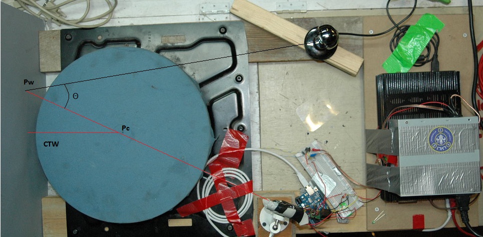
- sliceangle = the angle the platform has rotated from the start.
- Px = the X cordanet of the pixel we are trying to triangulate the location for.
- Pw = the X cordanet in pixals of the laser when it hits the wall from calibration.
- Pc = the X cordanet in pixals of the laser crossing the center of the platform.
- ctw = the distance in mm the center of the platform is to the back wall.
You may have noticed that the Z coordinate is not actually calculated. This is because we did not calculate it but just placed it off the Z axis based on its location in the image. This means that parts of objects that are closer are distorted and appear bigger in the scans than the parts that are farther away.
-
Showing what constants are set for calculation.
Calibration:
Calibration is a manual process that involves placing an object over the center point and taking a picture with the laser on. You then measure the X pixel location of both the object and the line on the wall.
-
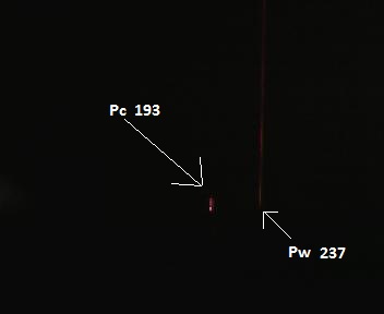
Calibration for current view from the camera.
-
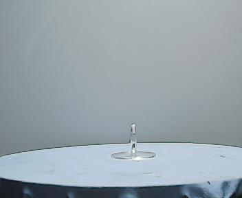
This is what it looks like with the lights on. using the stem of a plastic wine glass and a bit of rope.
What It Generates:
The scanner makes a few files, but only offers you one of them. As a backup plan when it looked like I may not finish the python code the scanner was set up to also return an animated gif of the object rotating. The animated gif is generated on every scan and is accessible from the web interface. Along with that gif is a folder holding every image that was taken in the scan. Lastly there is a .OBJ file generated when running "Scan with laser". This file holds the point cloud data that is spit out from the python script. It is in the same folder as the gif with the same name.
-
This is a gif of what the scanner sees.
-
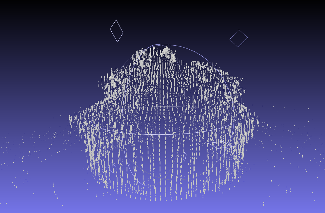
Cupcake Point Cloud
What's Next?
This scanner was a blast to make but was not all that functional. We are really happy with it's performance based on what was used to make it, but rather than upgrade it and replace everything in it part by part we plan to start from scratch with better hardware and software, as well as algorithms we have time to lay out properly. With the shortcomings on this scanner too long to list we look forward to building one that will fix at least a few of them. With that we are releasing all of the software "as is" and do not plan on maintaining it or fixing the issues it has. We hope that it can help people understand how it works and help them build scanners of there own.
Great work with good images! Is this scanner fully functional now?
Pingback: MAKE | Build a 3D Scanner Out of Junk… in 24 Hours
Great work, I wish I had been there to see that happen
I did something like this years ago as a high-school project.
http://www.importsoul.net/python/recycled-zero-cost-3d-scanner/
Pingback: ITé’å¹´èˆ » 3D scanner made in a day